1
Open the model and destination
Open the IFC in Studio. Create a new drawing in AutoCAD and select it in Connected Apps. Confirm the model units and the units you want in the DWG.
2
Define the drawing
3
Review the editable result
In AutoCAD, switch to an isometric view and inspect the generated entities and layers. Check the outside dimensions, wall heights, door gaps and window locations against the IFC. This Garden Office transfer contains 204 native 3D faces from 11 IFC objects, with millimetre units.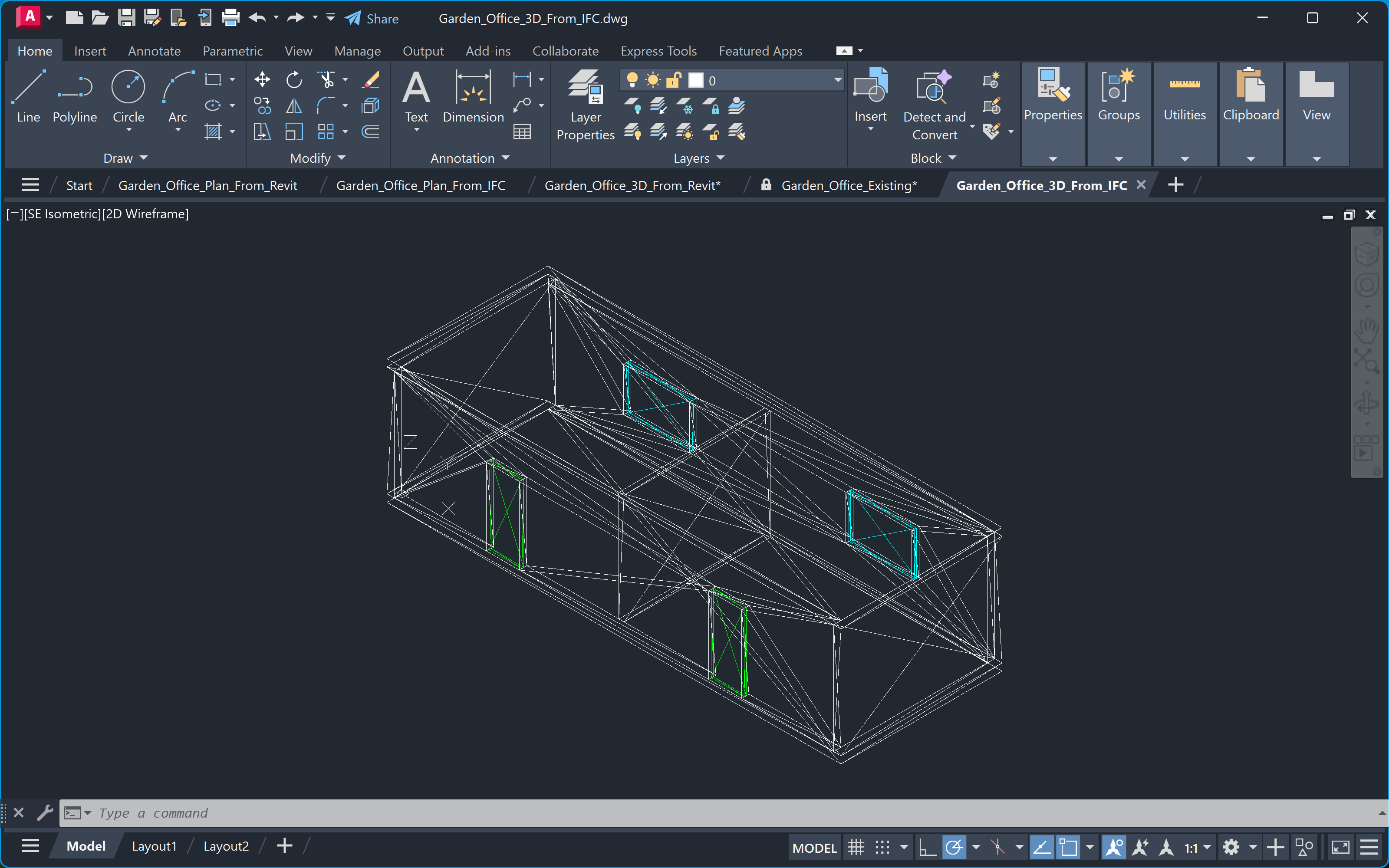
4
Save the DWG
Save the new drawing under a distinct name. Keep the IFC as the source model. Changes in the DWG do not automatically update the IFC.
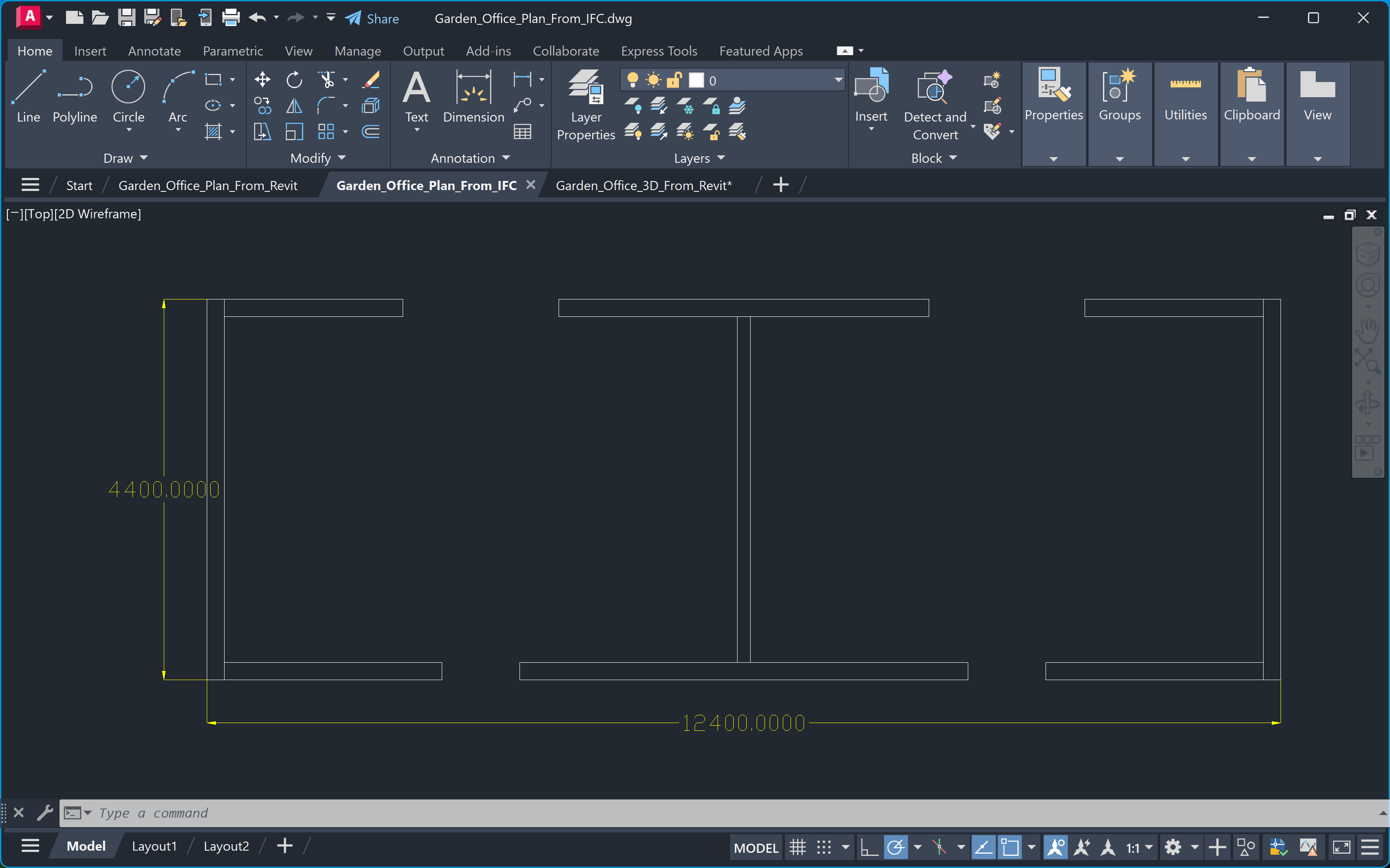
Optional: derive a 2D plan
Ask for a separate floor-plan drawing with a specified level and cut height. In this example, the horizontal cut is 1500 mm above the ground floor. Keep wall cuts and annotations on separate layers. A top view of the roof is not a floor plan. The Garden Office example produces nine closed wall-cut polylines and two editable dimensions. The outside dimensions are 12400 × 4400 mm. Openings appear as gaps in the wall cut; they are not Revit-style door or window objects.