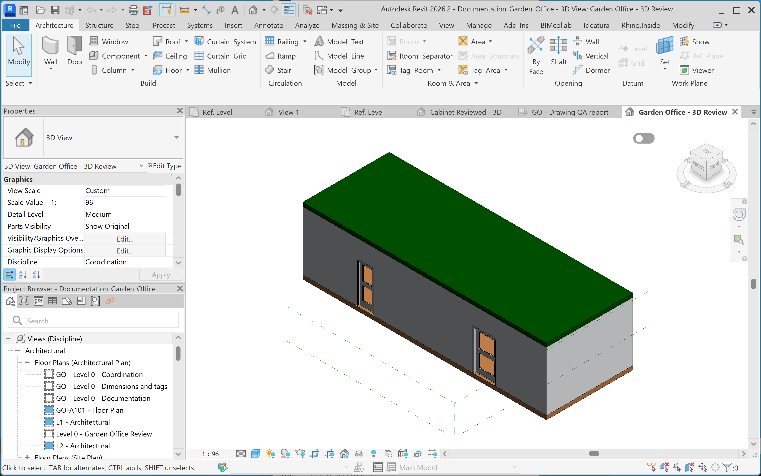
The clip compares the prepared source drawing with its reconstructed Revit model. It does not show a new AI modelling run. Use a measured DWG as the source for a new Revit model. Ask for native elements explicitly: placing the drawing as an import or link does not create editable Revit walls and openings.
1

Connect AutoCAD and Revit

Open the source DWG in AutoCAD and a destination project in Revit. Select both documents in Studio’s Connected Apps menu. Confirm the filenames before sending the task.
2

Read the drawing first
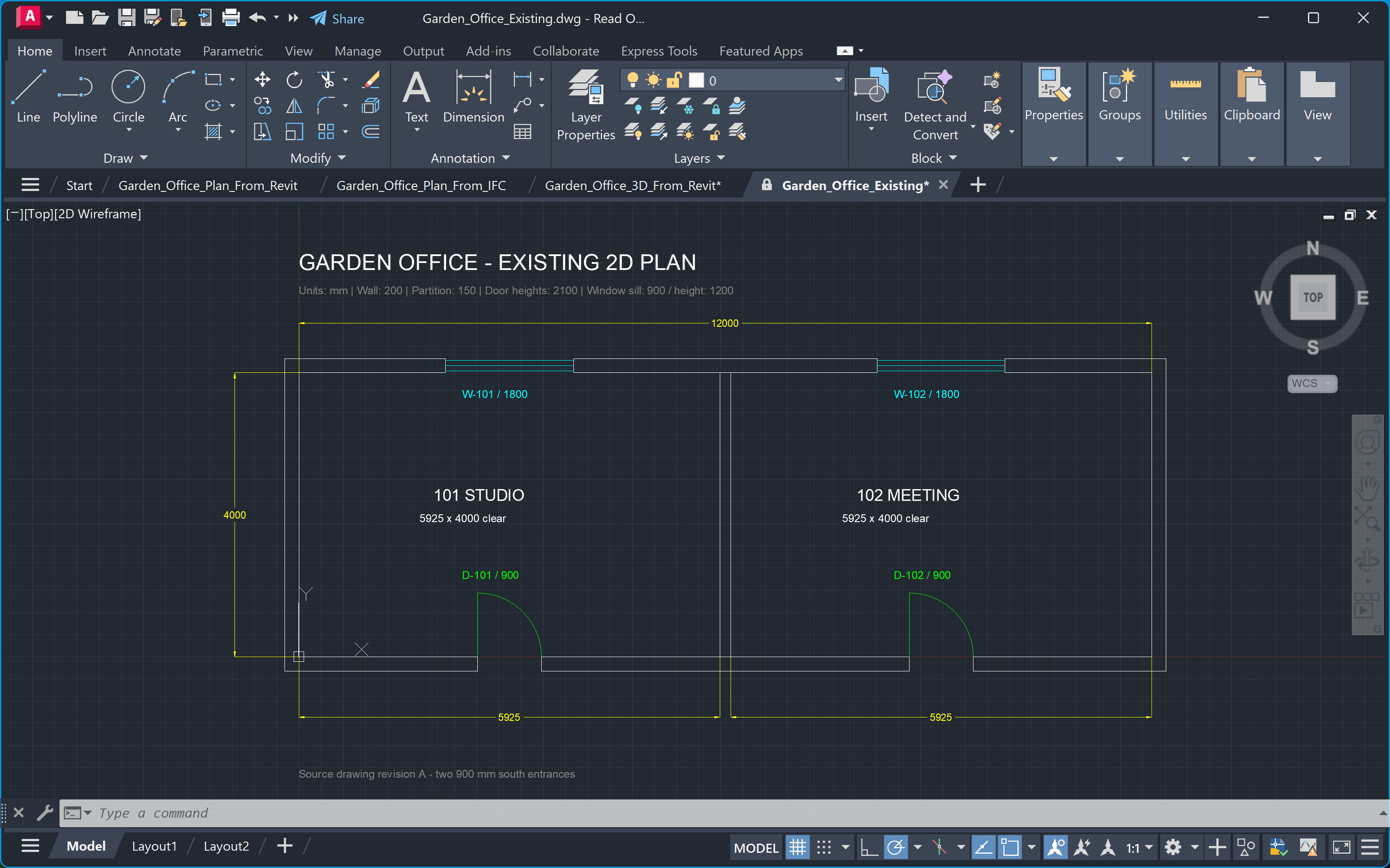
The measured Garden Office source drawing opened read-only in AutoCAD.
Agree on the destination level, origin, orientation, wall heights and opening sizes. If the source only contains a schematic door symbol, choose an appropriate Revit family rather than expecting its detailing to match the symbol exactly.
3

Create native elements

Let Ideatura build the model, then inspect both the plan and 3D view. Select a wall, door and window to check their Revit categories and parameters.The Garden Office model in Revit, ready for inspection in plan and 3D.
4

Compare and save

Compare the outside dimensions, clear room sizes, opening locations and door handing with the DWG. Check the wall cuts and sill heights in 3D, then save the Revit project.For the Garden Office example, compare the five native Revit walls with the drawing’s two-room layout. The source plan has a 12400 × 4400 mm outside footprint, 200 mm external walls and a 150 mm partition. Verify the hosted openings separately; matching the footprint alone does not establish that the model is correct.