1. Open the source drawing
Download the sample DWG and open it in AutoCAD. This synthetic sample uses millimetres: a 6000 × 4000 mm outer footprint, 200 mm walls, a centered south door and a north window. Read the dimensions and notes before modelling.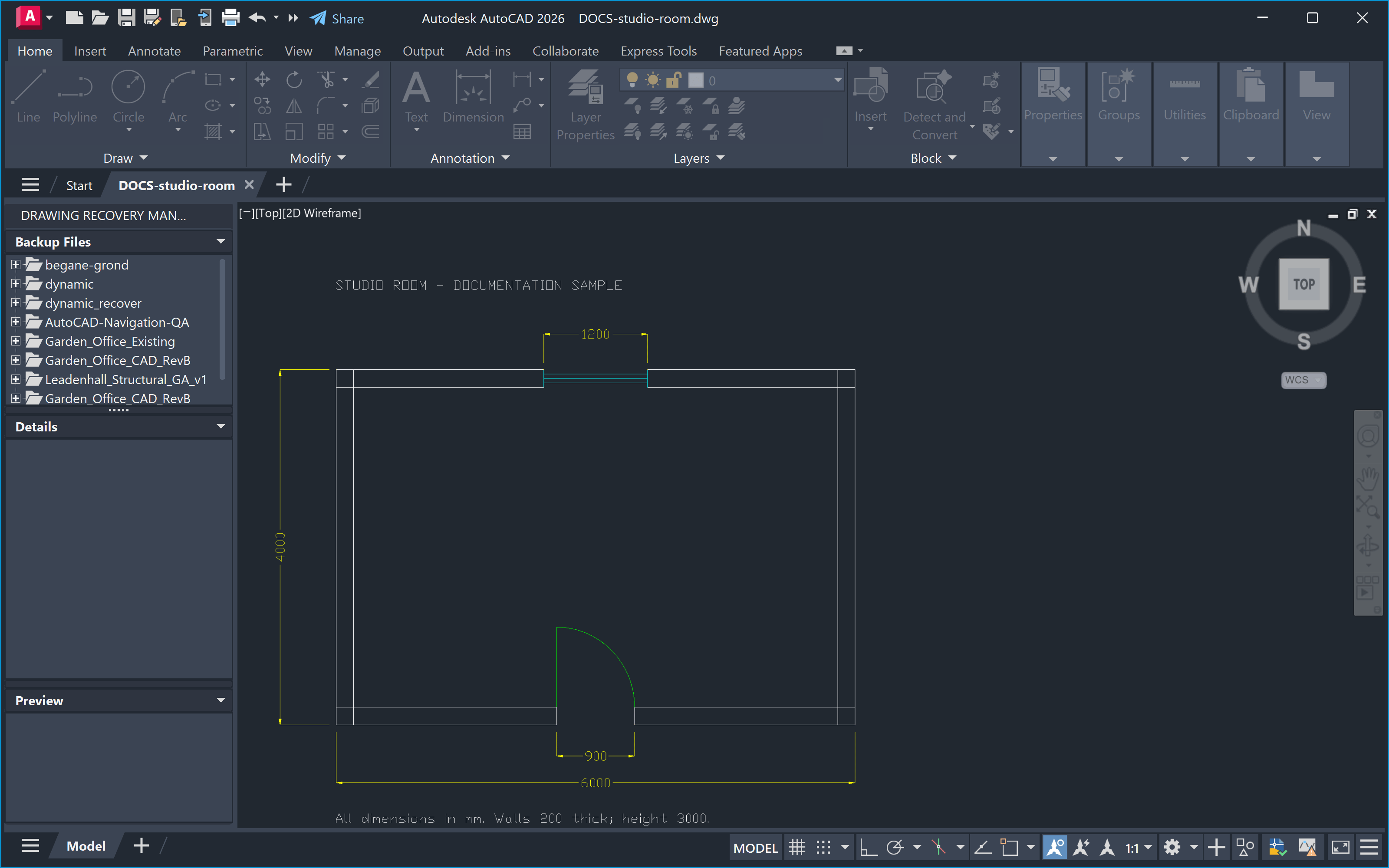
2. Connect both applications
In Studio, open Connected Apps, select both AutoCAD and Revit, and confirm the exact document names. Tell Studio to preserve the source DWG and existing Revit projects and create a new disposable metric project. This is a scope instruction, not an enforced read-only restriction. Use the open AutoCAD drawing as the source; attaching the binary DWG to the conversation was rejected in this attempt.3. Define the native reconstruction
Ask Studio to read the drawing’s vectors, dimensions and notes, then build native Revit walls, a floor and hosted openings. Preserve the southwest outside corner at 0,0, with Level 0 at zero elevation and no rotation or scaling.
The run created four native walls, one hosted door, one hosted window and one floor, without a CAD import standing in for the model. The source DWG remained unchanged.
4. Compare the model with the DWG
Inspect the plan for wall alignment, opening positions and door handing. The native result has the centered north window and south door with its west hinge and inward swing. Measured checks confirmed the 6000 × 4000 mm outside dimensions and 5600 × 3600 mm clear interior.